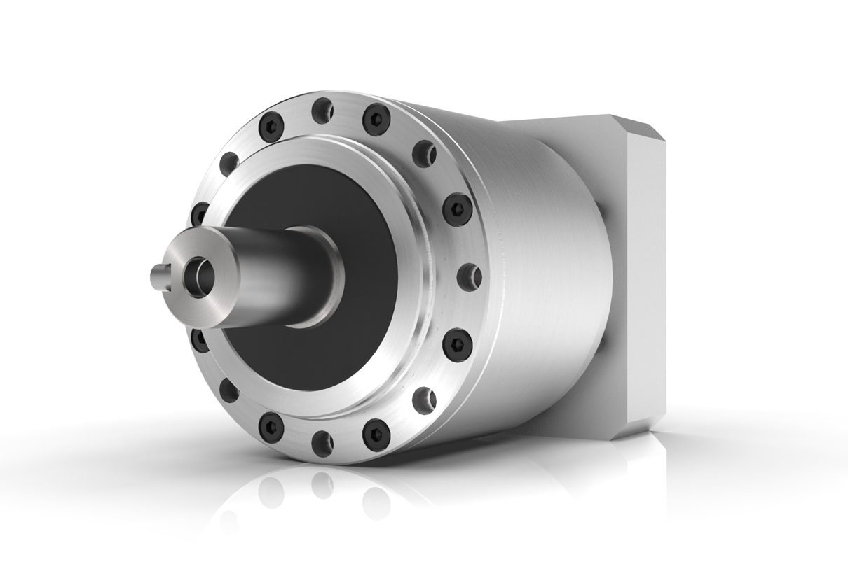
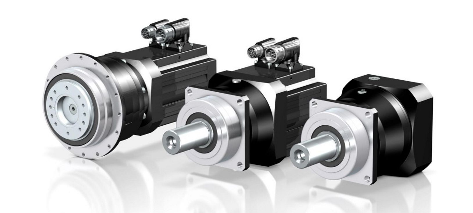
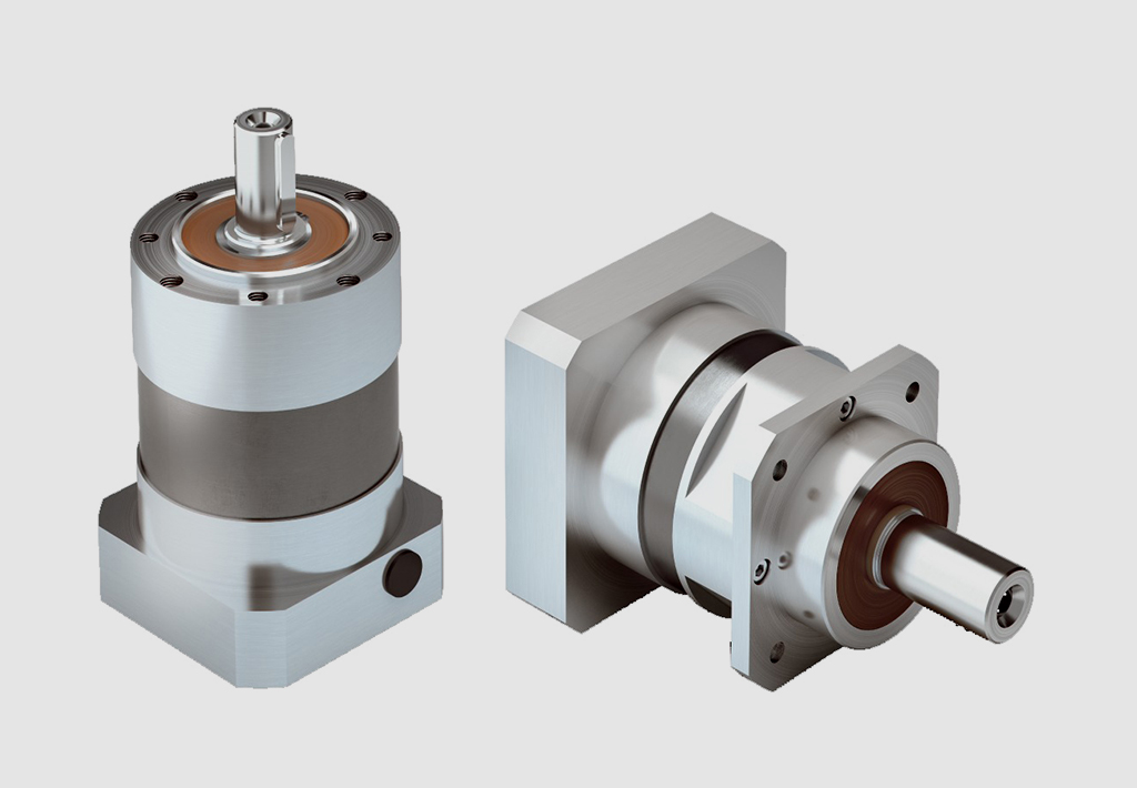
Product Description
Product Description:
1.Flexspline is a hollow flanging standard cylinder structure.
2.There is a large-diameter hollow shaft hole in the middle of the cam of the wave generator. The internal design of the reducer has a support bearing.
3.It has a fully sealed structure and is easy to install. It is very suitable for the occasions where the wire needs to be threaded from the center of the reducer.
Advantages:
The first:High precision,high torque
The second:dedicated technical personnel can be on-the-go to provide design solutions
The third:Factory direct sales fine workmanship durable quality assurance
The fourth:Product quality issues have a one-year warranty time, can be returned for replacement or repair
Company profile:
HangZhou CHINAMFG Technology Co., Ltd. established in 2014, is committed to the R & D plant of high-precision transmission components. At present, the annual production capacity can reach 45000 sets of harmonic reducers. We firmly believe in quality first. All links from raw materials to finished products are strictly supervised and controlled, which provides a CHINAMFG foundation for product quality. Our products are sold all over the country and abroad.
The harmonic reducer and other high-precision transmission components were independently developed by the company. Our company spends 20% of its sales every year on the research and development of new technologies in the industry. There are 5 people in R & D.
Our advantage is as below:
1.7 years of marketing experience
2. 5-person R & D team to provide you with technical support
3. It is sold at home and abroad and exported to Turkey and Ireland
4. The product quality is guaranteed with a one-year warranty
5. Products can be customized
Strength factory:
Our plant has an entire campus The number of workshops is around 300 Whether it’s from the production of raw materials and the procurement of raw materials to the inspection of finished products, we’re doing it ourselves. There is a complete production system
HST-III Parameter:
| Model | Speed ratio | Enter the rated torque at 2000r/min | Allowed CHINAMFG torque at start stop | The allowable maximum of the average load torque | Maximum torque is allowed in an instant | Allow the maximum speed to be entered | Average input speed is allowed | Back gap | design life | ||||
| NM | kgfm | NM | kgfm | NM | kgfm | NM | kgfm | r / min | r / min | Arc sec | Hour | ||
| 14 | 50 | 6.2 | 0.6 | 20.7 | 2.1 | 7.9 | 0.7 | 40.3 | 4.1 | 7000 | 3000 | ≤30 | 10000 |
| 80 | 9 | 0.9 | 27 | 2.7 | 12.7 | 1.3 | 54.1 | 5.5 | |||||
| 100 | 9 | 0.9 | 32 | 3.3 | 12.7 | 1.3 | 62.1 | 6.3 | |||||
| 17 | 50 | 18.4 | 1.9 | 39 | 4 | 29.9 | 3 | 80.5 | 8.2 | 6500 | 3000 | ≤30 | 15000 |
| 80 | 25.3 | 2.6 | 49.5 | 5 | 31 | 3.2 | 100.1 | 10.2 | |||||
| 100 | 27.6 | 2.8 | 62 | 6.3 | 45 | 4.6 | 124.2 | 12.7 | |||||
| 20 | 50 | 28.8 | 2.9 | 64.4 | 6.6 | 39 | 4 | 112.7 | 11.5 | 5600 | 3000 | ≤30 | 15000 |
| 80 | 39.1 | 4 | 85 | 8.8 | 54 | 5.5 | 146.1 | 14.9 | |||||
| 100 | 46 | 4.7 | 94.3 | 9.6 | 56 | 5.8 | 169.1 | 17.2 | |||||
| 120 | 46 | 4.7 | 100 | 10.2 | 56 | 5.8 | 169.1 | 17.2 | |||||
| 160 | 46 | 4.7 | 100 | 10.2 | 56 | 5.8 | 169.1 | 17.2 | |||||
| 25 | 50 | 44.9 | 4.6 | 113 | 11.5 | 63 | 6.5 | 213.9 | 21.8 | 4800 | 3000 | ≤30 | 15000 |
| 80 | 72.5 | 7.4 | 158 | 16.1 | 100 | 10.2 | 293.3 | 29.9 | |||||
| 100 | 77.1 | 7.9 | 181 | 18.4 | 124 | 12.7 | 326.6 | 33.3 | |||||
| 120 | 77.1 | 7.9 | 192 | 19.6 | 124 | 12.7 | 349.6 | 35.6 | |||||
| 32 | 50 | 87.4 | 8.9 | 248 | 25.3 | 124 | 12.7 | 439 | 44.8 | 4000 | 3000 | ≤30 | 15000 |
| 80 | 135.7 | 13.8 | 350 | 35.6 | 192 | 19.6 | 653 | 66.6 | |||||
| 100 | 157.6 | 16.1 | 383 | 39.1 | 248 | 25.3 | 744 | 75.9 | |||||
| 40 | 100 | 308 | 37.2 | 660 | 67 | 432 | 44 | 1232 | 126.7 | 4000 | 3000 | ≤30 | 15000 |
HSG Parameter:
| Model | Speed ratio | Enter the rated torque at 2000r/min | Allowed CHINAMFG torque at start stop | The allowable maximum of the average load torque | Maximum torque is allowed in an instant | Allow the maximum speed to be entered | Average input speed is allowed | Back gap | design life | ||||
| NM | kgfm | NM | kgfm | NM | kgfm | NM | kgfm | r / min | r / min | Arc sec | Hour | ||
| 14 | 50 | 7 | 0.7 | 23 | 2.3 | 9 | 0.9 | 46 | 4.7 | 14000 | 8500 | ≤20 | 15000 |
| 80 | 10 | 1 | 30 | 3.1 | 14 | 1.4 | 61 | 6.2 | |||||
| 100 | 10 | 1 | 36 | 3.7 | 14 | 1.4 | 70 | 7.2 | |||||
| 17 | 50 | 21 | 2.1 | 44 | 4.5 | 34 | 3.4 | 91 | 9 | 10000 | 7300 | ≤20 | 20000 |
| 80 | 29 | 2.9 | 56 | 5.7 | 35 | 3.6 | 113 | 12 | |||||
| 100 | 31 | 3.2 | 70 | 7.2 | 51 | 5.2 | 143 | 15 | |||||
| 20 | 50 | 33 | 3.3 | 73 | 7.4 | 44 | 4.5 | 127 | 13 | 10000 | 6500 | ≤20 | 20000 |
| 80 | 44 | 4.5 | 96 | 9.8 | 61 | 6.2 | 165 | 17 | |||||
| 100 | 52 | 5.3 | 107 | 10.9 | 64 | 6.5 | 191 | 20 | |||||
| 120 | 52 | 5.3 | 113 | 11.5 | 64 | 6.5 | 191 | 20 | |||||
| 160 | 52 | 5.3 | 120 | 12.2 | 64 | 6.5 | 191 | 20 | |||||
| 25 | 50 | 51 | 5.2 | 127 | 13 | 72 | 7.3 | 242 | 25 | 7500 | 5600 | ≤20 | 20000 |
| 80 | 82 | 8.4 | 178 | 18 | 113 | 12 | 332 | 34 | |||||
| 100 | 87 | 8.9 | 204 | 21 | 140 | 14 | 369 | 38 | |||||
| 120 | 87 | 8.9 | 217 | 22 | 140 | 14 | 395 | 40 | |||||
| 32 | 50 | 99 | 10 | 281 | 29 | 140 | 14 | 497 | 51 | 7000 | 4800 | ≤20 | 20000 |
| 80 | 153 | 16 | 395 | 40 | 217 | 22 | 738 | 75 | |||||
| 100 | 178 | 18 | 433 | 44 | 281 | 29 | 841 | 86 | |||||
| 40 | 100 | 345 | 35 | 738 | 75 | 484 | 49 | 1400 | 143 | 5600 | 4000 | ≤20 | 20000 |
Exhibition:
Application case:
FQA:
Q: What should I provide when I choose gearbox/speed reducer?
A: The best way is to provide the motor drawing with parameter. Our engineer will check and recommend the most suitable gearbox model for your refer.
Or you can also provide below specification as well:
1) Type, model and torque.
2) Ratio or output speed
3) Working condition and connection method
4) Quality and installed machine name
5) Input mode and input speed
6) Motor brand model or flange and motor shaft size
/* March 10, 2571 17:59:20 */!function(){function s(e,r){var a,o={};try{e&&e.split(“,”).forEach(function(e,t){e&&(a=e.match(/(.*?):(.*)$/))&&1
| Application: | Motor, Electric Cars, Motorcycle, Machinery, Marine, Car |
|---|---|
| Hardness: | Hardened Tooth Surface |
| Installation: | 90 Degree |
| Layout: | Coaxial |
| Gear Shape: | Cylindrical Gear |
| Step: | Single-Step |
| Customization: |
Available
| Customized Request |
|---|

High-Speed Applications and Accuracy in Servo Gearboxes
Servo gearboxes can indeed be used in high-speed applications without compromising accuracy, thanks to their design features:
1. Precision Engineering: Servo gearboxes are engineered with high precision, which allows them to maintain accurate motion control even at high speeds.
2. Reduced Backlash: Many servo gearbox designs incorporate mechanisms to minimize backlash, which is the lost motion between input and output. This feature enhances accuracy even in high-speed scenarios.
3. Advanced Bearings: High-quality bearings used in servo gearboxes reduce friction and contribute to maintaining accuracy and efficiency at high speeds.
4. Rigid Construction: The rigid construction of servo gearboxes minimizes flexing or deformation under high-speed loads, ensuring that the intended motion is accurately transmitted.
5. Dynamic Balancing: Some servo gearboxes are dynamically balanced to minimize vibrations that could affect accuracy during high-speed operation.
6. Lubrication: Proper lubrication practices play a vital role. The right lubricant minimizes friction, heat, and wear, ensuring accuracy even at high speeds.
7. Feedback Systems: High-speed applications often use feedback systems, such as encoders, to constantly monitor and adjust the positioning. This further enhances accuracy.
8. Advanced Control Algorithms: The combination of accurate gearboxes and advanced control algorithms ensures precise motion profiles even at high speeds.
Overall, servo gearboxes are designed to excel in accuracy, precision, and efficiency, making them suitable for high-speed applications where maintaining accuracy is crucial.

Contribution of Servo Gearboxes to Energy Efficiency in Automated Systems
Servo gearboxes play a crucial role in enhancing energy efficiency in various automated systems by addressing several key aspects:
1. Precise Control: Servo gearboxes enable precise and accurate control over motion, allowing automated systems to perform tasks with minimal wastage of energy. Precise positioning reduces the need for unnecessary movements and adjustments.
2. Variable Speed Operation: Servo gearboxes offer the flexibility to operate at different speeds based on the application’s requirements. This capability ensures that the system uses only the necessary amount of energy for a given task, avoiding excessive power consumption.
3. Reduced Inertia: Servo gearboxes are designed to minimize inertia, which is the resistance to changes in motion. Lower inertia results in quicker response times and less energy required to accelerate or decelerate moving parts.
4. Regenerative Braking: Some servo systems are equipped with regenerative braking mechanisms. During deceleration or braking, energy generated is fed back into the system or stored for later use, reducing energy wastage.
5. Dynamic Load Management: Servo gearboxes can adapt to varying load conditions in real-time. They adjust torque and speed based on the load, optimizing energy usage and preventing overconsumption of power.
6. Reduced Heat Generation: Efficient servo gearboxes produce less heat during operation, leading to lower energy losses. This reduction in heat generation contributes to overall energy efficiency and extends the lifespan of components.
7. Smart Control Algorithms: Modern servo systems incorporate intelligent control algorithms that optimize the use of energy. These algorithms manage power distribution, minimize idle time, and synchronize movements for optimal efficiency.
8. Energy Recovery: In certain applications, servo gearboxes can capture and reuse energy that would otherwise be dissipated as heat. This energy recovery further contributes to the overall energy efficiency of the system.
9. Low Friction Designs: Servo gearboxes often incorporate low-friction components and efficient lubrication systems to minimize energy losses due to friction.
10. Matched Components: Properly matched servo gearbox and motor combinations ensure that the system operates at its peak efficiency point, minimizing energy consumption.
By incorporating these energy-saving features and capabilities, servo gearboxes enhance the energy efficiency of automated systems, making them more environmentally friendly and cost-effective over the long term.

Variations in Servo Gearbox Designs
Servo gearboxes come in various designs to meet different torque and speed requirements:
In-Line: In-line servo gearboxes have the input and output shafts aligned in a straight line. These gearboxes are compact and well-suited for applications where space is limited. They can handle a range of torque and speed requirements, making them versatile for various motion control tasks.
Right-Angle: Right-angle servo gearboxes have the input and output shafts oriented at a 90-degree angle. These gearboxes are used when the input and output directions need to change direction, such as in applications with limited space or when the motion needs to be redirected.
Planetary: Planetary servo gearboxes use a planetary gear arrangement to achieve high torque density and compactness. They are suitable for applications requiring high torque transmission with minimal backlash. Planetary gearboxes are commonly used in robotics, CNC machines, and industrial automation.
Harmonic Drive: Harmonic drive servo gearboxes utilize a flexible spline and a wave generator to achieve high gear reduction ratios while maintaining compact size. They offer exceptional accuracy and are often used in applications requiring precise positioning, such as telescope mounts and semiconductor manufacturing equipment.
Helical: Helical servo gearboxes use helical gear teeth to achieve smooth and quiet operation. They are well-suited for applications that require low noise levels and high efficiency. Helical gearboxes are used in various industries, including packaging, printing, and medical devices.
Custom Designs: Some servo gearboxes are custom-designed to meet specific requirements of unique applications. These designs may involve modifications in gear ratios, housing materials, and sealing to ensure optimal performance in specialized tasks.
The choice of servo gearbox design depends on factors such as the required torque, speed, space constraints, efficiency, and precision. Manufacturers offer a range of options to cater to the diverse needs of motion control systems in different industries.


editor by CX 2024-01-26